Basic Mechanical
Basic Mechanical
Gear
A gear is a rotating machine part having cut teeth, which mesh with another toothed part to transmit torque. Geared devices can change the speed, torque, and direction of a power source. The pitch of two gear must be same and must mesh with each other, then only they work fine.

Gears work on the principle of mechanical advantage. This means that by using different gear diameters, you can exchange between rotational (or translation) velocity and torque.
As with all motors, by looking at the motor datasheet you can determine the output velocity and torque of your motor. But unfortunately for robots, motors commercially available do not normally have a desirable speed to torque ratio (the main exception being servos and high torque motors with built in gearboxes). For example, do you really want your robot wheels to rotate at 10,000 rpm at low torques? In robotics, torque is better than speed.
With gears, you will exchange the high velocity with a better torque. This exchange happens with a very simple equation that you can calculate:
Torque_Old * Velocity_Old = Torque_New * Velocity_New
Torque_Old and Velocity_Old can be found simply by looking up the datasheet of your motor. Then what you need to do is put a desired torque or velocity on the right hand side of the equation.
Gear types
Spur Gears (~90% efficiency)
 Spur gears are the most commonly used gears due to their simplicity and the fact that they have the highest possible efficiency of all gear types. Not recommend for very high loads as gear teeth can break more easily.
Helical Gears (~80% efficiency)
Helical gears operate just like spur gears, but offer smoother operation. You can also optionally operate them at an angle, too. Unfortunately, due to the complex shape, they are generally more expensive.
Sproket Gears With Chains (~80% efficiency)
Two gears with a chain can be considered as three separate gears. Since there is an odd number, the rotation direction is the same. They operate basically like spur gears, but due to increased contact area there is increased friction (hence lower efficiency). Lubrication is highly recommended.
Bevel Gears (~70% efficiency)
Bevel gears are good for changing the rotation angle. Unfortunately they suffer low efficiencies, so avoid use if possible.
Rack and Pinion (~90% efficiency)
Rack and Pinion is the type of gearing found in steering systems. This gearing is great if you want to convert rotational motion into translational. Mathematically, use radius = 1 for the straight 'gea
Worm Gears (~70% efficiency)
Worm gears have a very high gearing ratio. To mathematically calculate, consider the worm gear as a single tooth. Another advantage to the worm gear is that it is not back-drivable. What this means is only your motor can rotate the main gear, so things like gravity or counter forces will not cause any rotation. This is good say if you have a robot arm holding something heavy, and you don't want to waste power on holding torque. The efficiency is low, but lubrication really helps.
Planetary Gears (~80% efficiency)
Planetary gears have the highest commercially available gear ratios you would ever want to put on a robot. But since they are somewhat complicated, you would never need to build one, just use it. The datasheet should tell you the gearing ratio - I just wanted you to know if you need a really really high gearing ratio for a robot, planetary gears are the way to go. Even better, some planetary gears offer multiple gearing ratio's that are user configurable!
Shafts
A shaft is a rotating machine element which is used to transmit power from one part/machine to another. They are usually circular in cross section. It may also be defined as, Any thing that is rotated in the hole.
Coupling
A coupling is a device used to connect two shafts together at their ends for the purpose of transmitting power.The primary purpose of couplings is to join two pieces of rotating equipment while permitting some degree of misalignment or end movement or both.

Bearing
A bearing is a machine element that constrains relative motion to only the desired motion, and reduces friction between moving parts. Bearing holds rotating components such as shafts or axles within mechanical systems, and transfer axial and radial loads from the source of the load to the structure supporting it.

Fastener
A fastener is a hardware device that mechanically joins two or more objects together. In general, fasteners are used to create non-permanent joints i.e joints that can be removed or dismantled without damaging the joining components.
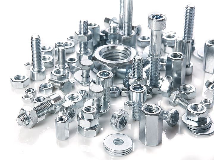
Examples: Nut-Bolt, Screw , rivet etc
The pitch of Nut and Bolt must be same to work properly.
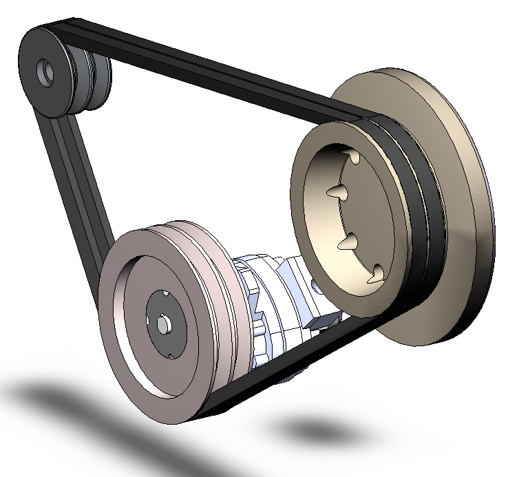
Belt
A belt is a loop of flexible material used to link two or more rotating shafts mechanically, most often parallel. Belts may be used as a source of motion, to transmit power efficiently or to track relative movement. They can transmit power to parallel shafts mainly.
Chain
A chain is a serial assembly of connected pieces, called links, typically made of metal, with an overall character similar to that of a rope in that it is flexibles. May be designed for lifting, pulling, securing, tighting, etc
Linkage
A linkage is an assembly of bodies connected to manage forces and movement. It connects two joint.
Wheel
Generally Circular, that moves the things from one place to another together with the wheels. They roll over the surface to move. For better stability The number of wheels are increased accordingly. The wheel combinations of 3, is the minimum number of wheels required for stability.
For same shaft connected to wheels of different diameter, For one revolution, The larger diameter wheel will travel greater distance.
How Does Wheel Size Affect My Robot?
Angular Velocity
The velocity (feet per second) of a robot is directly related to the angular velocity, w (in radians per second - NOT RPM) of the motor and the radius of the wheel, R (ideally in meters or feet, so when calculating v it is in meters per second or feet per second).
w = v / R
Re-arranging this equation, we find the velocity of the robot:
v = w*R
Most motor manufacturers provide the no load RPM, so to convert RPM to radians per second, you need the following equation:
1 rev/min = 2*pi/60 rad/sec
Often, a "Voltage constant", Kv is provided by the manufacturer; for example, a motor may be rated at Kv= 2.4 Volts / 1000 RPM which correlates the RPM to the voltage.
This is the theory, now the reality: It's not always possible to operate a motor at its nominal voltage, and we often need to operate it at a few volts higher or lower. Keep in mind that the "nominal" voltage runs the motor at near peak efficiency, which is still never 100%; and as you move away from the nominal voltage, the efficiency drops, so the motor needs more current to provide the same torque, consuming the battery even faster. Next, keep in mind that not all motors can be operated at all voltages and all motors have a maximum rated voltage. The Voltage constant usually applies over a small range around the nominal voltage, and outside this range, the curve is not linear and not only will the motor not be operating efficiently, the output will not be anything like what you predict with the equations.
Distance Traveled
To get an idea of how far your robot has traveled, you need to know the circumference of the drive wheel:
Circumference (C) = 2*pi*R
Distance traveled = wCt (where 'w' is in rad/sec and 't' is in seconds) So what to do? Here are some useful tips:
Choose smaller sized wheel for flat terrain, larger wheel for more "off-road" (or large obstacles) Proportional to the size of the robot (choosing a wheel proportional to the size of the robot will usually mean the motor you will need is also proportional, and the robot has a better chance of moving at a decent speed) See what wheels are out there - not all wheels have mounting hubs designed for all motors Keep in mind that a larger wheel may require a more powerful motor; we'll go into more detail about this in a future article.
Use the same wheel for all drive motors: as you can see, changing the radius affects both the speed and the distance traveled: you don't want one wheel "fighting" against the other.
Degrees of freedom

Degree of freedom is the number of independent parameters that define its configuration. It is the number of parameters that determine the state of a physical system and is important to the analysis of systems of bodies in mechanical engineering, aeronautical engineering, robotics, and structural engineering. It basically defines the translation and rotational axis.
The position of a single railcar (engine) moving along a track has one degree of freedom because the position of the car is defined by the distance along the track.